Tensegrity
Tensional Integrity – stability through a balance of isolated compression and continuous tension.

Tensegrity Engineering: Principles, Components, and Optimization
Tensegrity Definition
Tensegrity structures achieve stability via isolated compressive elements suspended in a continuous tensile network. They offer lightweight design, high strength-to-weight ratio, and efficient load distribution.
Principles
Stability arises from equilibrium between prestressed tension and compression. For a structure with $ n $ nodes and $ m $ members, equilibrium at node $ i $ is:
$$ \sum_{k \in \mathcal{K}_i} f_k \frac{\mathbf{r}_j - \mathbf{r}_i}{l_k} + \mathbf{F}_i = 0 $$
In matrix form: $ \mathbf{A} \mathbf{f} = -\mathbf{F} $. For self-stressed systems: $ \mathbf{A} \mathbf{f} = 0 $, with stability requiring positive semi-definite stiffness.
Compressive and Tensional Members
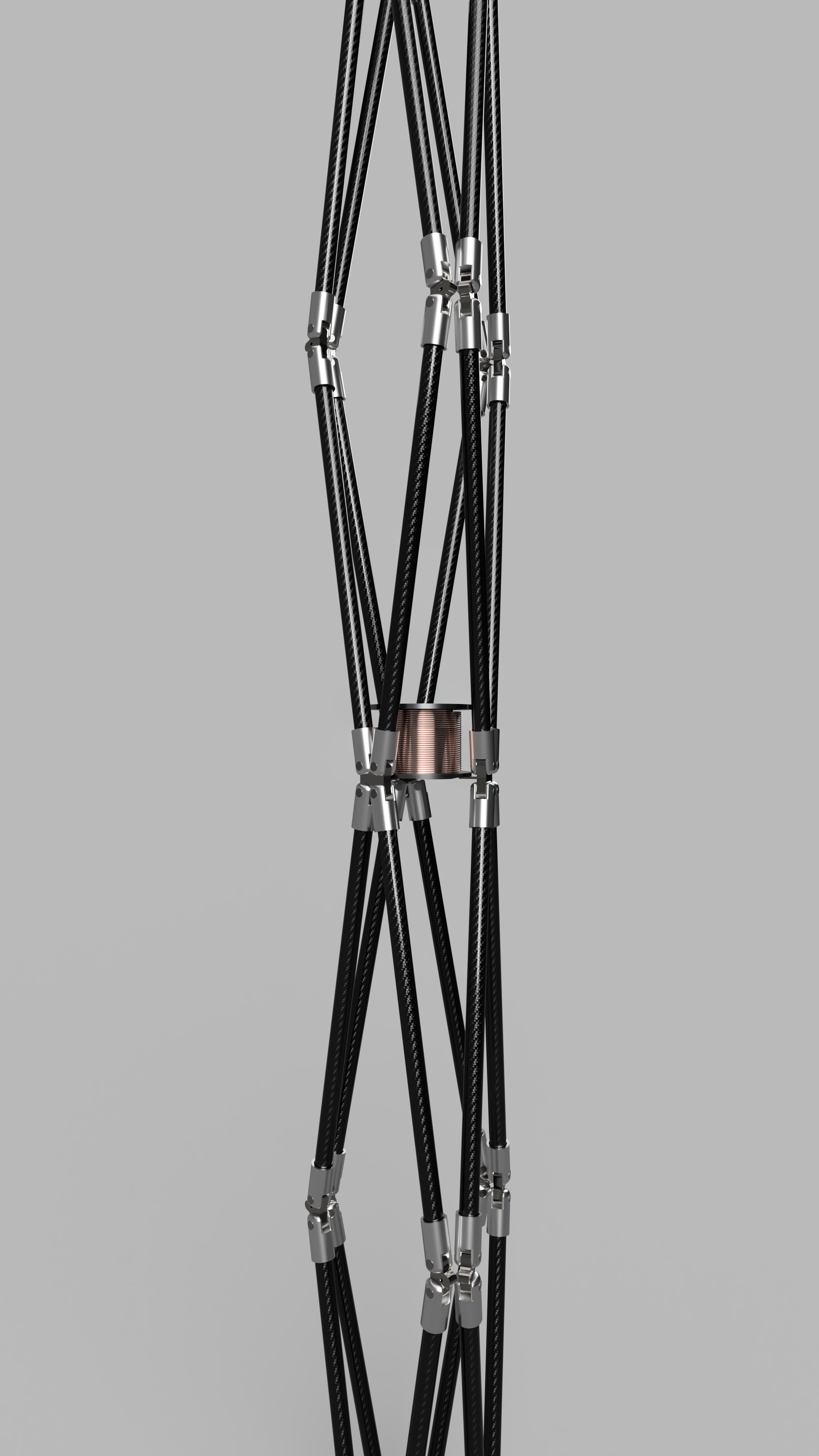
Compressive Members (Struts): Rigid rods resisting compression; isolated, no direct contact. Materials: aluminum, steel, carbon fiber.
Tensional Members (Cables): Flexible elements carrying tension only; continuous network providing prestress. Materials: steel wire, Kevlar, polymers.
Members operate in pure compression or tension, avoiding shear and bending.
Buckling and Yielding Equations
Buckling (Struts)
Euler's critical load:
$$ P_{cr} = \frac{\pi^2 E I}{(K L)^2} $$
Where $ E $: Young's modulus, $ I $: moment of inertia, $ L $: length, $ K $: effective length factor.
Yielding (Cables)
Tensile stress:
$$ \sigma = \frac{F}{A} < \frac{\sigma_y}{n} $$
Where $ \sigma_y $: yield strength, $ n $: safety factor.
Optimization
Minimize objectives (e.g., mass $ m = \sum_k \rho_k A_k l_k $)) subject to constraints:
$$ \min_{\mathbf{x}} , f(\mathbf{x}) \quad \text{s.t.} \quad g_i(\mathbf{x}) \leq 0, , h_j(\mathbf{x}) = 0 $$
Constraints include buckling/yielding limits and equilibrium. Use GA, PSO, or SQP. Form-finding: force density method solving $ \mathbf{C}^T \mathbf{Q} \mathbf{C} \mathbf{r} = 0 $.
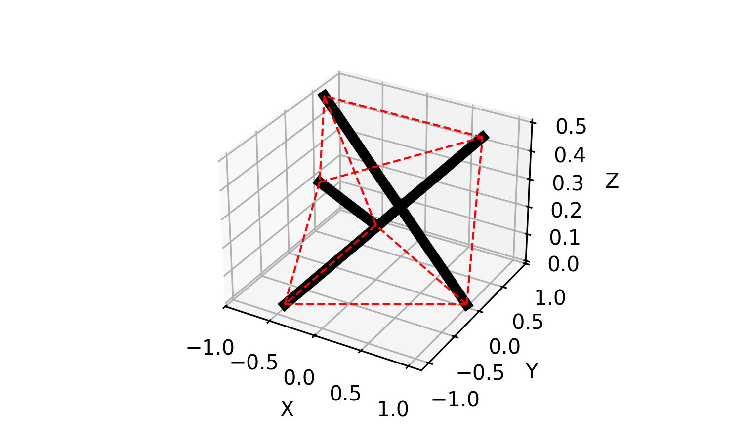
Design Topologies
Class k: Max struts per node (Class 1: no contact).
Prismatic: e.g., 3 struts, 9 cables.
Polyhedral: e.g., icosahedron for domes.
Simplexes: Tetrahedron (4 struts, 6 cables), octahedron (6 struts, 12 cables).
Deployable: Foldable for space applications.
Biomimetic: Chain-like for flexibility.